eLearning | Computer Based Training | Systems Simulation
Basic Electronic Circuits > Bistable Circuit (Flip-Flop)
A bistable circuit, or flip-flop, can be created in many ways. Our example on this page is made from 2 transistor switches, cross connected to use the output from each transistor as the input for the other. The circuit also features 4 resistors and 2 capacitors.
This type of circuit can be utilised to store data, therefore flip-flops are used in the memory circuits of computers.
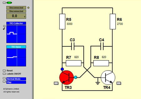
With power on, the circuit will always assume and remain in one of 2 states - either the left transistor will be on or the right transistor will be on. In either state, the circuit is stable.
The normal method of changing over the state of the circuit is to turn off the transistor that is currently on. This can be achieved by connecting its base to earth, reducing its potential to zero. As a result, this raises the potential at the collector and also at the base of the other transistor to turn it on.
Using the integrated digital multimeter and oscilloscopes on the left of the screen, circuit operation can be demonstrated or observed. The instructor or the student is also provided with the flexibility of running the simulation in various modes, such as Key Event Mode, which automatically pauses the simulation whenever events designated as key events occur.
This item is part of a package of 3 interactive circuits which include: